|
|
2 years ago | |
|---|---|---|
| static | 2 years ago | |
| templates | 2 years ago | |
| .gitignore | 3 years ago | |
| readme.md | 2 years ago | |
| requirements.txt | 3 years ago | |
| temp.jpg | 3 years ago | |
| workbook.py | 2 years ago | |
readme.md
Workbook
1. intro/overview
Welcome to the Workbook: a tool to keep track and annotate configurations for different instruments and facilitate learning process.
Nowadays digital instruments can easily save sound presets and load them as necessary. When it comes to analog synths although, to recall a patch often means to manually turn knobs, connect cables and flip switches. While messing up with all these handles is for sure one of the joys of playing with such instruments, remembering which configuration generated that specific sound effect can be tough.
The Workbook offers a practical way to store snapshopts of how knobs were set and cables connected. It is an online interface where it's possible to create interactive version of instruments and archive their different configurations. When creating a new configuration, also referred as patch, the position of the knobs and their value are stored together with a drawing of wires and cables connections.
Each patch has a name and a description, as well as the possibility to upload audio snippets to help make some sense out of the tangle of cables that sometimes sounds amazing and some other seems just a broken radio.
2. what + why / intentions
- open extendible
3. add instrument
The Workbook is open and extendible. Instead of being modeled on a specific device, it offers some guidelines to create an interactive panel starting from an SVG image of the instrument.
SVG, that stands for Scalable Vector Graphics, is a format where images are described with a language based on tags similar to HTML. Instead of being saved as a list of pixels, pictures are stored as text files that can be read, inspected and even modified just by writing. That doesn't mean that to create an SVG file it's necessary to code it by hand: all the major graphics editor can export in .svg format, and that means that creating an instrument for the workbook is easy and accessible.
An SVG image usually looks like this
<svg width="100" height="100">
    <circle cx="28" cy="28" r="14" fill="red"/>
    <rect x="57" y="66" width="34" height="12" fill="green"/>
</svg>
Even without seeing the picture, we can read that there are a red circle and a green rectangle. What's more is that we can give names to elements, organize them in groups to create different layers, make things visible and invisible, and so on.
The SVG file for an instrument in the workbook is composed of three groups: one for the graphics, one for the socket and one for the parameters.
The graphics group contain all the visuals of the panel. It can be as fancy as possible, without any particular restrictions. The code that transform the SVG into an interactive panel is not really concerned about the contents of this group, so it can just be anything.
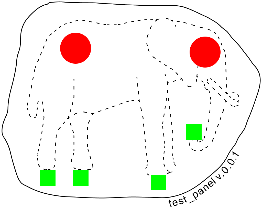
The socket group contains a series of elements that indicate the position for input and output for patch cables. Things you can connect together. They are represented by rectangles of color #00FF00, each one with an id that states its name.
The params group contains a series of elements that indicate the position for knobs. Each knob is represented by a circle of color #FF0000 and an id stating the name of the parameter. The current version of the Workbook implements only knobs as control surface. Fader and button are coming soon!
The test_panel.svg for example looks like this:
<svg width="1024" height="817">
    <g id="graphics">
    <!-- omitted for clarity, just a mess of svg paths -->
    </g>
    <g id="params">
        <circle id="back" cx="295.5" cy="188.5" r="60.5" fill="#FF0000"/>
        <circle id="eye" cx="801.5" cy="203.5" r="60.5" fill="#FF0000"/>
    </g>
    <g id="sockets">
        <rect id="feet" x="157" y="666" width="60" height="60" fill="#00FF00"/>
        <rect id="faat" x="590" y="683" width="60" height="60" fill="#00FF00"/>
        <rect id="foot" x="286" y="666" width="60" height="60" fill="#00FF00"/>
        <rect id="nose" x="728" y="486" width="60" height="60" fill="#00FF00"/>
    </g>
</svg>
How to get to this clean structure it's a matter of trial and error with the SVG editor you are using.
Figma
Figma is an online vector graphics editor.
During the development of the workbook we used mainly SVG exported from Figma.
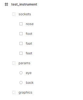
The panel was a frame with the three groups graphics, params and sockets.
Every element in the params and sockets groups was named after the name of the parameter or socket.
Notice how the name of the layers maps 1:1 to the id in the exported SVG. This is thanks to the option in the export section *Include "id" attribute. *
Inkscape
Exporting from Inkscape requires a bit more effort.
Ideally start to organize your contents in the Object tab. Create the three layers and use them as container for the other element.
When you are happy with the results it's time to set the id. Unfortunatly the Inkscape treats id and object label as different things, generating ids authomatically with generic names. It is possible though to edit the id attribute from the XML Editor present in Inkscape. From the XML Editor (ctrl shift x) it's possible to set the id of the elements.
Remember to do it for the groups as well as for the elements!
When it comes to exporting SVG from Inkscape there are listed several options: choose export optimized svg
This will open a window to select several options. Set it like this:
[Options]
Number of significant digits for coordinates: 5

[ ] Shorten color values
[x] Convert CSS attributes to XML attributes
[ ] Collapse groups
[ ] Create groups for similar attributes
[ ] Keep editor data
[ ] Keep unreferenced definitions
[x] Work aroud renderer bugs

[SVG Output]
Document options

[ ] Remove the XML declaration
[ ] Remove metadata
[ ] Remove comments
[x] Embed raster images
[ ] Enable viewboxing

Pretty-printing

[x]  Format output with line-breaks and indentation

Indentation characters: Space
Depth of indentation: 1

[ ] Strip the "xml:space" attribute from the root SVG element

[IDs]

[ ] Remove unused IDs
[ ] Shorten IDs
[x] Preserve manually created IDs not ending with digits
Check your exported file!
Probably there will be some small correction to do by hand, for example ensuring that the elements in params have the fill="#FF0000" attribute, and that the ones in sockets have the fill="#00FF00".

